Today I worked on learning Unix. I looked up some popular commands online and I also started looking through the Unix for Mac textbook. Here is a copy of the text:

Here is a list of the commands I learned:
-
$ ls -1 (list vertically with one line per item)
-
$ ls - h1 (long form, human readable)
-
$ ls - h1t (long form, human readable, sorted by time)
-
$ ls -a1 (list all)
-
Pwd (print working directory)
-
Cd _____ (change directory)
-
Cd ../ (go back to old directory)
-
Cd (back to home directory)~
-
Cd / (root directory)
-
Cd ~/——/ (certain directory in home)
-
Mkdir —— (make new folder)
-
Rmdir —— (delete folder)
-
Cp —— —— (copy file)
-
Mv —— —— (rename file)
-
Rm —— (delete file)
-
Find . -name —— (find file)
-
mv —— —— (move file to directory)
-
Du (list files and sizes)
-
Cat ——.txt (view text document)
-
Cat > ——.txt (create text doc)
-
Less —— (view txt file)
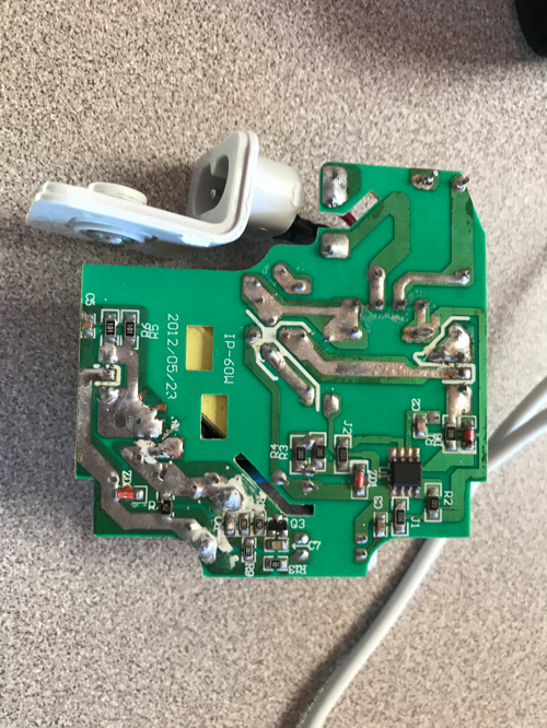
I also used my new toolkit for the first time to take apart an old MacBook charger that had caught on fire in order to try and identify the problem. Once I took it apart, you could instantly see that there was heat damage on the board in multiple different spots. Oliver and I used a multimeter to measure how many ohms of resistance was between some of the damaged joints to check if any of them shorted. The resistance between one of the voltage regulators and a resistor joint there was over 200 ohms of resistance. We checked the same joints on one of the other chargers that Oliver took apart (this one wasn’t damaged) and there was only 30 ohms present. Our theory is that the extra resistance prevented some of the excess heat from flowing from the voltage regulator to the heatsink (as the two are connected) and therefore the heat was redirected, causing the rest of the heat damage on the board and eventually leading to the fire. We want to test this theory more tomorrow.
Here is the broken charger:
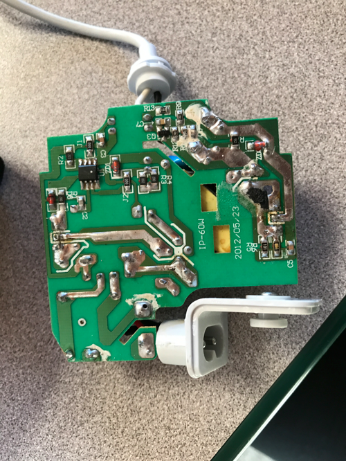
Here is the working charger:
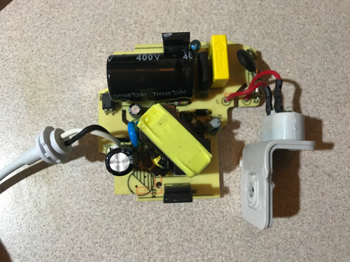
This is the parts of the charger:
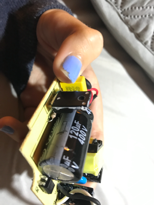
This is the voltage resistor we think is faulty (the resistor in the background is the one we measured the resistance with):
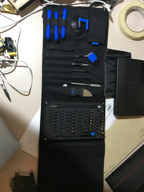
Here is my new toolkit :) :
Comments